Freeing Ever Given: the engineering behind the Suez Canal salvage
How ground support, dredging, buoyancy, ballast and coordinated tug forces interact, using the March 2021 salvage as a sourced engineering case study.
By Largest Ship in the World · 11 min read · Published
More in ENGINEERING CASE STUDY →Running a giant series →Try the engineering lab →
Contents · 15 sections
A six-day obstruction, a much larger engineering problem
Ever Given grounded during a northbound Suez Canal transit on 23 March 2021. It was refloated on 29 March. Those dates became familiar around the world, but the engineering cannot be reduced to a picture of a large ship and a small excavator. The recovery involved understanding how a damaged operating situation had changed the hull’s support, then coordinating excavation, water level and applied forces to recover controlled movement.
The Panama Maritime Authority’s investigation and Boskalis’s salvage accounts answer different questions. The investigation examines the incident and its circumstances. The contractor explains aspects of the recovery in which its team participated. This article keeps those roles distinct. It uses the event to explain general engineering principles, while labeling illustrative calculations and diagrams as such. It does not reproduce the salvors’ working model or claim that a single publicly reported detail explains the entire operation.
Sources: [1] Panama Maritime Authority: final investigation report, hosted copy ↗ [2] Boskalis: refloating announcement, 29 March 2021 ↗
.jpg)
Start with what is documented
The flag-state report is the appropriate source for the passage, bridge events and conclusions of that investigation. It should be read as a complete document, including its chronology and evidence, rather than mined for one sentence that supports a preferred explanation. Wind, ship handling and the constrained waterway were discussed extensively after the grounding, but a short social-media clip cannot independently resolve their respective contributions.
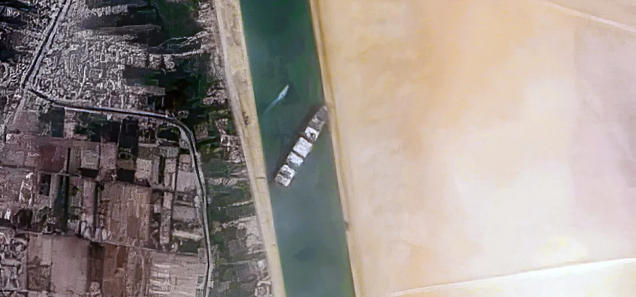
The narrow part of the canal also matters geometrically. A vessel’s full length, beam and draft interact with the usable channel, not just the apparent width visible from above. A satellite photograph shows surface relationships; it does not show the complete underwater bank profile. The voyage map on this site therefore locates the entrance, grounding area and Great Bitter Lake for context. Its connecting lines are schematic, not an invented replay of the ship’s movement or rudder orders.
Sources: [1] Panama Maritime Authority: final investigation report, hosted copy ↗
Grounding changes the support system
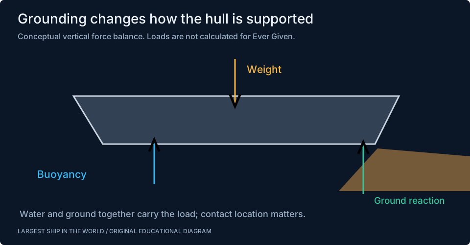
A freely floating ship is supported by buoyancy distributed along its immersed hull. Its total weight is balanced by the upward force associated with displaced water. Once part of the hull rests on the ground, another force enters the balance: ground reaction. Water and seabed can now carry different portions of the load. The original floating condition no longer describes the entire support system.
That change is important even before anyone attempts to pull. Concentrated contact can produce local loads and alter the bending distribution along a long hull. The place where the ship touches the bank matters as much as a statement that it is aground. A bow embedded in material, a stern contacting a bank and a broad hull resting on a relatively even bed are different conditions. A salvage assessment needs the actual contact geometry and ship condition, not only the total displacement.
Why pulling harder is not the complete answer
An applied towing force must overcome the effects resisting the intended motion while staying within the limits of the towing arrangement and the casualty. Ground contact can create friction and mechanical restraint. Embedded portions of the hull may need clearance before they can move in the desired direction. Increasing force without changing those conditions can increase loads without producing useful movement.
A simple block resting on a rough surface provides a limited analogy. Reducing its supported weight can reduce friction, while removing an obstacle changes the available path. A ship is far more complex because water, soil, structure and geometry all interact, but the analogy explains why salvage combines several interventions. Tugs are not the entire solution merely because they are the most visible source of force at the final moment. Their effectiveness depends on the condition the other work has created.
Dredging changes the geometry of the problem
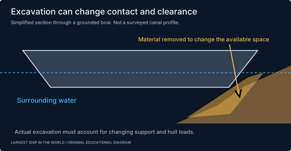
Boskalis’s account describes the combination of salvage and dredging expertise with locally available equipment. Excavation around the grounded vessel changed the material restraining it and the space available for refloating. The useful way to understand this work is to ask where contact remained and what movement would become possible as material was removed.
The process is more selective than simply making the whole canal deeper. Excavating in one area can change support in another, and a hull must remain within acceptable loading conditions as that happens. Equipment also has limits of reach, access and production in the particular ground. Photographs show moments in that process rather than the complete excavation plan. Our diagram is therefore a conceptual section through a grounded bow; it intentionally avoids inventing dimensions, soil properties or an exact cut profile from an overhead image.
Sources: [3] Boskalis Horizons: account of the salvage operation ↗
Water level can change the force balance
If water rises around a grounded hull, the potential buoyant support can increase. That can reduce the part of the load carried by the ground and change the conditions for movement. The relationship depends on the hull’s immersed geometry, the grounding constraints and whether the vessel is able to change attitude. It is not the same as lifting a rigid object by a known amount with a crane.
For an original scale example, an assumed waterplane area of 15,000 square metres and an increase in water level of 0.3 metres correspond to 4,500 cubic metres of additional displaced volume if the geometry allows it. At an assumed seawater density of 1.025 tonnes per cubic metre, that represents about 4,613 tonnes of potential buoyant support. This is not a calculated value for Ever Given. It demonstrates why a modest water-level change can matter for a very large hull, while the real effect requires the actual casualty model.
Ballast can redistribute weight rather than simply remove it
The contractor’s account describes using the ship’s ballast system to improve the refloating situation. That may seem counterintuitive if ballast is understood only as extra weight. Its location matters. Changing the distribution can alter trim and the loads at particular contact areas, even when the total mass alone does not explain the effect.
A simple beam analogy helps. Move a weight towards one end of a supported beam and the reactions at its supports change. A grounded ship adds buoyancy, flexible structure and complex contact, so the analogy cannot determine a real transfer plan. It does explain why the question is where the weight acts, not merely how many tonnes are aboard. Our ballast article covers the separate issues of trim, free surface and structural loading. In a casualty, those relationships must be evaluated together with damage and ground support.
Sources: [3] Boskalis Horizons: account of the salvage operation ↗
Tug placement creates both force and moment
Tugs can contribute to translation, rotation or a combination. A pull near one end of the vessel creates a different turning moment from the same pull nearer the centre. Towline angle determines the components of force that act along and across the hull. Several tugs therefore form a coordinated force system; their individual ratings cannot simply be added without considering direction and the actual operating condition.
For a schematic example, a 400-kilonewton transverse force applied 150 metres from a reference point creates a moment of 60 million newton-metres. The arithmetic illustrates the value of a long lever arm. It is not the documented force or geometry of any tug in the operation. The practical task includes suitable connection points, towline loads, communication and the movement expected when restraint changes. The final successful pull was part of a changing situation created by the whole salvage effort.
Sources: [2] Boskalis: refloating announcement, 29 March 2021 ↗
Refloating one end is not the end of the operation
A ship can regain some movement while another part remains constrained. That intermediate condition may change the force directions and create a new pivot-like behaviour. A freed stern and a restrained bow, for example, present a different control problem from a vessel free at both ends. Observing rotation is therefore not enough to declare that the whole ship has regained an unrestricted floating condition.
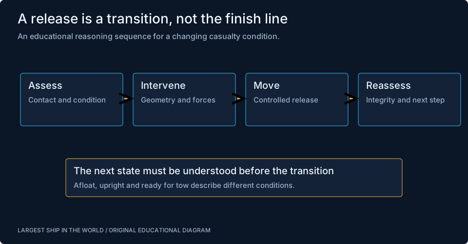
This distinction explains why early progress reports during a salvage can be both accurate and incomplete. They may describe a significant movement without establishing that the casualty can yet be towed away. The engineering team needs to understand the new position, contact and load distribution before the next action. A timeline should preserve that sequence rather than compressing every intermediate success into one instantaneous event. Controlled recovery is a series of states, each with its own questions.
The refloating moment needs control too
Boskalis records successful refloating on 29 March 2021 in cooperation with the Suez Canal Authority. Recovering buoyancy and movement was a major milestone, but movement itself had to remain controlled. Forces that were useful while the hull was restrained could have different effects once resistance changed. The canal remained a confined place in which to manage a large vessel.
The general engineering lesson is that the destination state must be planned along with the release. A load being freed can accelerate or rotate as restraints disappear. Towing arrangements and the intended path need to account for that transition. Our sequence diagram therefore ends with controlled movement and reassessment, not merely a checkmark beside ship afloat. That is a conceptual explanation of the task, not a replacement for the operation’s actual commands or an instruction for handling another grounded ship.
Sources: [2] Boskalis: refloating announcement, 29 March 2021 ↗
Structural integrity remains part of the calculation
A hull can experience changing local and global loads during grounding and recovery. Contact pressures, towing forces, ballast changes and buoyancy all influence that loading. An apparently successful displacement of the vessel does not itself prove that every part of the structure is undamaged. Assessment continues because movement and integrity are different questions.
The same distinction appears in many engineering projects. A bridge component can be moved into position while still requiring connection checks; a ship can be afloat while still needing inspection. For a casualty, the assessment concerns the actual condition and the demands of the next stage. Publicly visible dimensions and photographs do not provide enough information to calculate those margins. This site therefore avoids inventing a residual-strength figure or calling a force safe solely because a generic specification appears large enough.
A canal is a system, not an empty strip of water
Channel depth, banks, current, passing traffic and the rules of the waterway shape a transit. Ship response also depends on speed and loading. The wider lesson of a canal casualty is not simply that the ship was long. The interaction between the vessel and its operating environment needs to be understood before, during and after the passage.
This is why our dimensional canal checker does not claim to authorize a transit. It compares selected measurements with stated envelopes. It cannot reconstruct water level, dynamic under-keel clearance, local operating restrictions or the ship’s handling condition on a particular day. A useful educational tool makes that boundary visible. The stopping-and-turning guide supplies the next layer of understanding, including why heading, track and the space swept by the hull are different quantities.
Sources: [5] Wärtsilä: squat ↗ [6] Wärtsilä: manoeuvring characteristics ↗
How to read the photographs
The satellite image in this article gives a clear plan view of the obstruction. It shows the long hull across the waterway and the relationship to the banks. It does not show underwater damage, ground-contact pressure or the complete dredged profile. Those missing quantities are precisely the ones a technical assessment must investigate rather than estimate from appearance.
A tug photograph has a similar limitation. The number of visible vessels does not establish the force being applied at that instant. A towline may be slack, angled or working under a changing load. An excavator image shows a piece of equipment at one stage of a broader effort. Treating images as evidence of visible conditions makes them valuable; asking them to prove unobservable loads creates false precision. Captions should make that difference clear instead of inviting a dramatic but unsupported conclusion.
What this case teaches about large ships
Ever Given’s recovery brings several topics together. Buoyancy and ballast changed the support problem. Excavation changed contact and clearance. Tugs applied forces and moments. The hull imposed structural constraints, while the canal constrained the possible movement. The successful result emerged from those relationships and coordinated work rather than a single universal trick for freeing a ship.
For further reading, start with the investigation for the incident and the contractor accounts for the recovery. Then use our cutaways, ballast lab and ship-handling guide to explore the underlying mechanisms. The vessel profile and gallery keep the identity and images attached to the same ship. This evidence-first approach makes the case more interesting, not less: the real achievement lies in solving a changing physical problem while preserving control over a very large object in a tightly constrained space.
Sources: [1] Panama Maritime Authority: final investigation report, hosted copy ↗ [3] Boskalis Horizons: account of the salvage operation ↗ [4] Boskalis: 2021 annual report ↗
A better way to compare salvage methods
Compare interventions by the variable they change. Excavation alters the surrounding material and clearance. A water-level change alters available buoyancy. Ballast changes weight distribution. Tug work applies external force and moment. Inspection supplies evidence about the condition that constrains all four. This classification is more useful than ranking equipment by how dramatic it looks. It also explains why a method that succeeds at one casualty may be unsuitable elsewhere: the dominant restraint, accessible work area and structural condition can all be different.
Sources & further reading
An editorial explainer based on the technical, research and industry references below.