Life inside a ship’s engine room: the systems that keep a giant moving
A detailed tour from fuel tanks and cylinders to cooling water, electricity, freshwater and the engineers who keep the machinery working.
By Largest Ship in the World · 11 min read · Published
More in MACHINERY & LIFE AT SEA →Running a giant series →Try the engineering lab →
Contents · 15 sections
The engine is only the centre of the story
An engine room is a collection of connected systems that turns stored energy into propulsion and keeps the rest of the ship habitable. The largest engine may dominate photographs, but it cannot work for long without cooling, lubrication, fuel preparation, air, electricity and controls. A ship also needs water, ventilation, sewage handling, refrigeration and fire protection. Much of that work continues even when the propeller is stopped.
The layout reflects the vessel’s purpose. A container ship with a mechanically driven propeller has a different arrangement from a passenger ship using electric propulsion. A historic steam-turbine tanker differs from both. This tour explains the common functions without presenting one machinery space as a template for the entire fleet. The most useful way to read an engine-room photograph is to ask what each system supplies, what it removes and which other equipment depends on it.

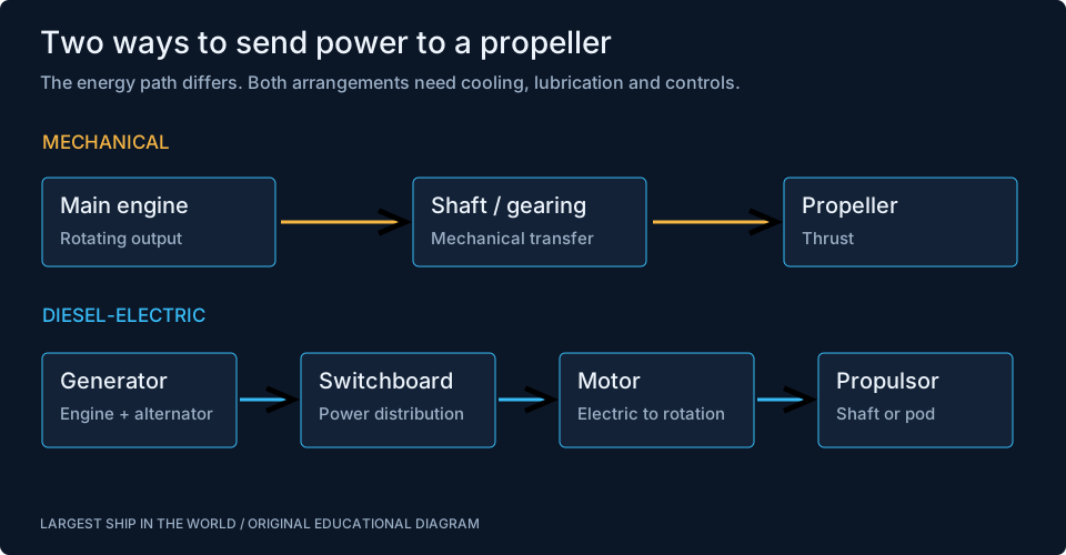
One engine room can contain several different power paths
In a conventional mechanical arrangement, the main engine’s rotating shaft ultimately drives a propeller. Low-speed two-stroke engines can be matched directly to a suitable propeller speed. Other arrangements use reduction gearing. Separate generator sets supply electrical services, although shaft generators and other configurations can connect the mechanical and electrical systems in additional ways.
In a diesel-electric arrangement, engines turn generators, electricity passes through switchboards and converters, and motors turn the propellers. The machinery that generates power need not sit on the same straight shaft line as the propulsor. This provides layout flexibility but adds electrical equipment and control requirements. Fuel is another dimension: a ship can use different fuels while retaining an electrical propulsion architecture. Saying LNG-powered identifies an energy source; it does not, on its own, tell us whether the propeller is mechanically or electrically driven.
Sources: [1] MAN Energy Solutions: S46ME-C8.6 project guide ↗ [4] ABB: Azipod electric propulsion ↗
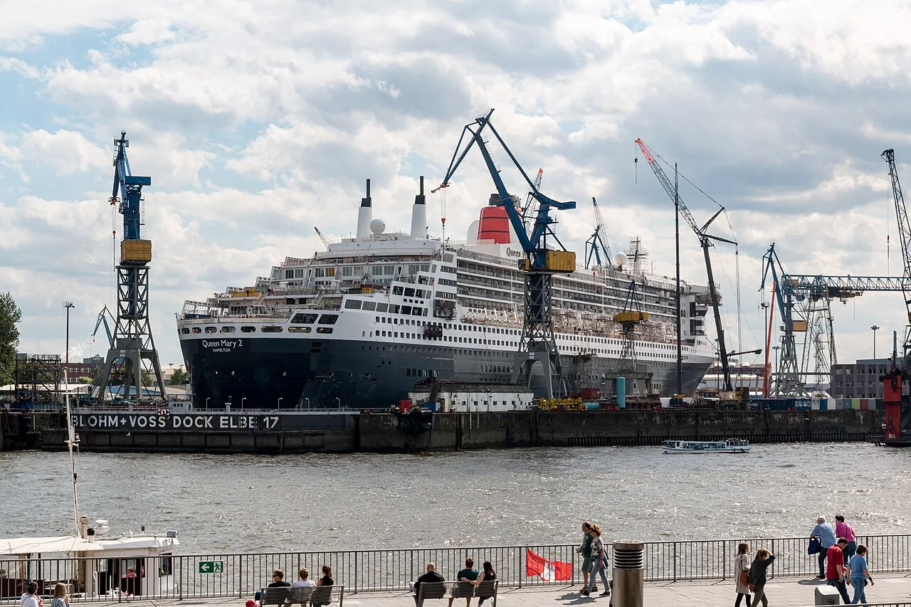
The scale of a slow-speed engine
A large low-speed engine stretches through more than one working level. Access platforms let engineers reach cylinder heads, fuel equipment and other components, while lower levels serve the crankcase and associated machinery. A crosshead arrangement separates parts of the piston motion and guide system from the crankshaft mechanism. The supporting structure must transmit forces into the ship, not simply hold a heavy machine in place.
Its physical size is not evidence that it runs at the highest rotational speed. Large marine engines can turn slowly while producing high torque. Power depends on torque and rotational speed together. A relatively slow shaft delivering a very large turning effort can therefore transmit enormous power. Comparing revolutions per minute alone with a car engine is misleading. The scale also affects maintenance: lifting arrangements, spare parts, overhead clearance and access routes are planned parts of the machinery installation.
Fuel takes a journey before reaching a cylinder
Fuel stored aboard is not always ready to be sent directly to an injector. Depending on the fuel and machinery, the system may include settling, separation, filtration, heating and pressure control. Water and contaminants can damage equipment or disrupt combustion. The purpose of preparation is to supply fuel within the engine maker’s requirements, rather than merely move it from a large tank to a smaller pipe.
Different fuel types require different treatment and handling arrangements. A diagram for heated residual fuel should not be casually reused as a description of LNG or methanol equipment. The pressure, temperature, material and safety requirements differ. This is why a fuel-conversion project involves more than changing a label beside the bunker connection. Storage, conditioning, supply, controls and crew procedures have to work as one system. The engine itself is only one part of that conversion.
Lubrication supports motion and reveals condition
Lubricating oil separates surfaces, carries away heat and can transport material that tells engineers something about wear. Pressure and temperature are important, but so are trends and contamination. A value still within an allowed range can become informative when compared with its normal pattern. The aim is to understand the condition of the machinery, not simply wait for an alarm threshold.
Some engines have distinct cylinder-lubrication and circulating-oil functions. The oils and their consumption should not be treated as interchangeable. Sampling, purification and filter inspection can provide different kinds of evidence. Consider a simple analogy: a single photograph of a road says less about traffic than a sequence over an hour. Machinery observations work similarly. Repeated measurements under comparable conditions help distinguish a developing problem from a normal change in load, temperature or operating mode.
Cooling is a chain of heat transfers
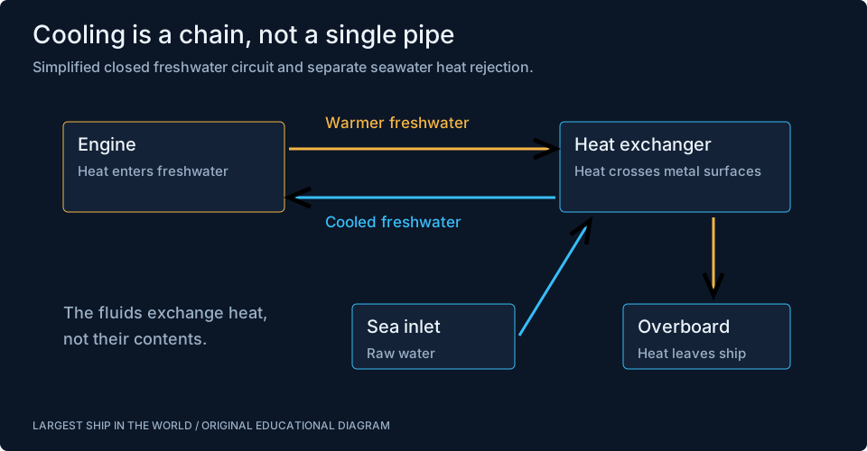
Not all the energy released by combustion reaches the propeller or generator. Heat also leaves through exhaust and cooling systems. Many installations keep a treated freshwater circuit around machinery and transfer its heat to seawater through heat exchangers. This reduces the need to expose internal engine surfaces directly to raw seawater. Separate circuits or temperature levels can serve equipment with different cooling needs.
A heat exchanger needs flow on both sides and a usable temperature difference. Fouling, restricted flow or a changing seawater temperature can affect performance even if the main engine has not changed. The visible symptom may appear at one machine while the underlying issue lies elsewhere in the cooling chain. Engineers therefore follow the system rather than assuming the hottest component is the source of every fault. Valves, strainers, pumps and exchanger surfaces can all influence the final result.
Sources: [3] Alfa Laval: marine systems and services ↗
Air, exhaust and recovered energy
Combustion needs oxygen, so a powerful engine must receive a substantial flow of air. Turbocharging uses energy in exhaust gas to drive a compressor that supplies intake air. The details differ among engine designs, but the connection illustrates how energy that would otherwise leave the cylinder can support the next combustion process. Exhaust flow is part of the operating balance rather than just an unwanted by-product.
Some ships recover useful heat from exhaust to produce steam or support other services. That can reduce the need to burn additional fuel for those demands. Recovery is not free energy: available temperature, operating load, fouling, pressure losses and the equipment’s limits matter. A system that works well at sustained sea load may behave differently in port. Energy diagrams should therefore show both the useful output and the conditions that make it available, rather than claiming that every unit of waste heat is recoverable.
Electricity keeps the rest of the ship alive
Generators supply pumps, controls, lights, navigation equipment and many other consumers. On a passenger vessel, hotel loads can include ventilation, cooking, cold storage and entertainment spaces as well as essential services. On a cargo vessel, refrigerated containers can add a major electrical demand. The load changes during manoeuvring, cargo operations and different weather conditions, so generation is managed rather than fixed at one setting throughout the voyage.
A switchboard connects sources and consumers through protective devices. Its arrangement affects what happens when a fault occurs and which sections can continue operating. Redundancy is not simply counting generators: a shared dependency can still disable several machines. Useful engineering questions include how equipment is separated, how loads are restored and what happens if a component fails during a demanding operation. The ship’s design and approved procedures determine those answers; a generic machinery diagram can only introduce the relationships.
A useful fuel-consumption calculation
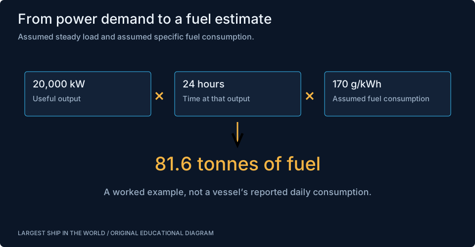
Specific fuel consumption relates fuel mass to useful energy output, often expressed as grams per kilowatt-hour. For an original example, assume a machine produces 20,000 kilowatts continuously for 24 hours at 170 grams per kilowatt-hour. Multiplication gives 81,600,000 grams, or 81.6 tonnes of fuel. These are assumed values chosen to make the arithmetic visible, not a measured daily figure for Emma Maersk or a modern cruise ship.
The calculation also exposes common mistakes. Installed power is not necessarily power used. A maximum rating multiplied by every hour of a voyage can overstate consumption. A quoted main-engine figure may omit generator fuel, boilers or other consumers. Changes in load and efficiency also matter. To compare two real operating days, we would need consistent boundaries and comparable conditions. The meaningful question is what energy was delivered, by which machinery, over what interval, and how the fuel was measured.
Freshwater, refrigeration and the invisible hotel
People aboard need reliable drinking water, sanitation, food storage and ventilation. Some ships produce freshwater from seawater using evaporation or membrane processes, while also taking water from shore. The choice and capacity depend on the vessel. Refrigeration protects food and other temperature-sensitive loads. These systems can appear secondary beside the propulsion engine, yet their failure can have immediate consequences for the people or cargo aboard.
Provisioning is connected to machinery too. Cold rooms require electricity and heat rejection. Galleys need ventilation and fire protection. Laundry adds water and heating demand. A passenger ship’s hotel operation makes these links particularly visible, but a small cargo crew also depends on them throughout an ocean passage. Thinking in connected services avoids the idea that the engine room is only active while the ship is moving. In port, propulsion may be quiet while many auxiliary systems continue working.
What engineers actually monitor
An engineer’s watch combines instrument readings with observation, communication and comparison against expected conditions. Alarms call attention to changes, but routine rounds can reveal vibration, leakage, unusual noise or a component becoming hotter than normal. The control room provides an overview; local inspection supplies another perspective. Neither should be treated as a complete substitute for the other.
The International Safety Management framework places ship operations within an organized system of responsibilities and procedures. For a reader, that helps explain why an engineering job includes documentation and handovers alongside physical work. A task may affect equipment used by another watch or department. Recording what was changed, isolated or observed preserves information that would otherwise leave with the person finishing a shift. Good machinery management is therefore partly about making the next decision with a reliable picture of the system.
Maintenance is a scheduling problem as well as a technical one
A component can need attention before it fails outright. Planned maintenance attempts to identify suitable intervals and opportunities, informed by maker guidance, operating experience and condition. Work that affects propulsion, electrical supply or essential services has to be coordinated with the ship’s schedule and other available equipment. A spare part aboard is useful only if the crew can access, lift and install it under suitable conditions.
Dry docking opens another set of opportunities. Underwater fittings, propellers and hull areas become accessible, while machinery work may be grouped with surveys and upgrades. Yet taking equipment apart creates its own risks and demands verification when reassembled. The maintenance plan therefore needs to include return to service, not only removal and replacement. From a design perspective, access space and lifting routes are productivity features. A compact installation that is difficult to maintain can impose costs throughout the vessel’s life.
The human environment matters
Machinery spaces can be hot, noisy and physically demanding. Access may involve ladders and multiple platforms. Protection, communication and suitable working arrangements are part of the job, not decorative additions to an engineering drawing. A planned task that looks short on paper may require preparation, coordination and recovery time around the actual work.
IMO and ILO material on work and rest highlights the importance of fatigue management at sea. The Maritime Labour Convention also addresses living and working conditions, including accommodation and food. This article does not describe a universal watch schedule because arrangements differ by ship and operation. The central point is that machinery reliability depends on people who can perform their work effectively. A system designed without considering workload, access and usable information is incomplete, even if every individual component meets its specification.
Sources: [6] IMO: seafarers’ hours of work and rest ↗ [7] ILO: Maritime Labour Convention ↗
Failures reveal the connections
Flooding in a machinery space can affect more than the machine nearest the leak. Electrical equipment, pumps, lubrication and access routes may share the same physical environment. A loss of one service can complicate recovery of another. Maersk’s 2013 account of Emma Maersk’s flooding and onward tow is a documented example of how a machinery incident becomes an operational recovery involving the whole vessel.
Pollution control is another connection. Bilge water, sludge and other waste streams require appropriate collection and treatment or landing arrangements. Their management is distinct from the process of getting fuel into an engine. It is not enough to describe a ship as efficient because its propeller is well matched; the handling of waste and the integrity of supporting systems also belong in the engineering picture. The relevant records and equipment vary by stream, so diagrams should keep those paths distinct.
Sources: [8] IMO: pollution prevention ↗ [9] Maersk: Emma Maersk flooding and onward journey, 2013 ↗
Reading an engine-room image with better questions
Look first for the power path: which machine drives which shaft or generator? Then trace the support systems: where do fuel, air, oil and cooling water enter, and where do heat and waste leave? Notice the platforms, cranes and clear spaces that allow people to maintain the installation. A room full of pipes becomes easier to understand when each pipe belongs to a function.
Finally, connect the machinery to the ship’s purpose. A liner may need sustained propulsion and substantial hotel power. A tanker has cargo-transfer demands that differ from those of a container ship. The interactive cutaways show these broad arrangements, while the operating guide discusses the people and supplies around them. The engine room is the place where all those requirements meet. Its achievement is not just producing power, but delivering dependable services through changing conditions for the whole voyage.
Watch the engineering in action
Sources & further reading
An editorial explainer based on the technical, research and industry references below.
- MAN Energy Solutions: S46ME-C8.6 project guide ↗
- Alfa Laval: fuel and oil treatment ↗
- Alfa Laval: marine systems and services ↗
- ABB: Azipod electric propulsion ↗
- IMO: International Safety Management Code ↗
- IMO: seafarers’ hours of work and rest ↗
- ILO: Maritime Labour Convention ↗
- IMO: pollution prevention ↗
- Maersk: Emma Maersk flooding and onward journey, 2013 ↗