How giant ships stop and turn: momentum, rudders, pods and tugboats
Follow a manoeuvre from the bridge command to the forces in the water, with worked examples, original diagrams and a close look at why stopping takes time.
By Largest Ship in the World · 11 min read · Published
More in SHIP HANDLING →Running a giant series →Try the engineering lab →
Contents · 14 sections
A command is only the beginning
A giant ship changes course by applying forces to the water around it. Propellers generate thrust, rudders create sideways force, and tugs can push or pull at selected points on the hull. To stop, the ship must lose its forward momentum through resistance and, when commanded, opposing thrust. There is no friction brake that can clamp onto the sea. Every manoeuvre therefore has a time history: the command, the machinery response, the development of force and the eventual movement of the hull.
This explains an apparently puzzling harbour scene. A ship may already have its engines producing astern thrust while it continues travelling forward. A vessel turning to starboard can sweep its stern to port. The bridge can point almost along the channel while the whole hull drifts sideways. Understanding those differences makes ship handling much easier to read. It also explains why a measurement of length or installed power cannot, by itself, tell us how much room a particular ship needs.
Sources: [1] Wärtsilä: rudder ↗ [2] Wärtsilä: manoeuvring characteristics ↗


Momentum is the starting point
Momentum equals mass multiplied by velocity. The relevant ship mass is displacement, including hull, machinery, cargo, fuel, water and everything else aboard. Gross tonnage is an index of enclosed volume and must not be substituted into this calculation. Deadweight is carrying capacity rather than the complete mass. Two vessels with similar gross tonnage can therefore have quite different momentum at the same speed.
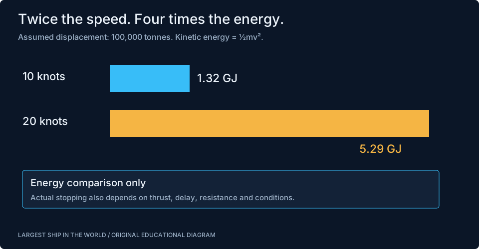
Consider an explicitly hypothetical ship displacing 100,000 tonnes. At 10 knots, approximately 5.14 metres per second, its kinetic energy is about 1.32 gigajoules. At 20 knots, that rises to approximately 5.29 gigajoules. Doubling speed doubles momentum but quadruples kinetic energy. These figures follow from one half of mass multiplied by speed squared. They are an energy comparison, not a claimed stopping trial for an existing vessel. Water accelerated around a manoeuvring hull adds further hydrodynamic complexity beyond this elementary calculation.
Why there is no universal stopping distance
A ship’s stopping performance depends on its initial speed and loading, the propulsion arrangement, the time needed to develop astern thrust and the surrounding conditions. A published trial result has a defined starting condition. Change that condition and the distance may change. Stopping in deep open water is also different from deciding where to begin slowing for a bend, a pilot station or a berth.
For a simple thought experiment, a constant opposing force of one million newtons acting on our hypothetical 100,000-tonne mass would produce a deceleration of 0.01 metres per second squared. Ignoring every other force, a starting speed of 5 metres per second would take 500 seconds and 1,250 metres to dissipate. Actual resistance and propeller thrust vary with speed, so this is not a usable ship-handling formula. It demonstrates why very large forces can still require patience when the mass is large.
Sources: [2] Wärtsilä: manoeuvring characteristics ↗ [3] IMO: Standards for Ship Manoeuvrability, MSC.137(76) ↗
What happens after an astern order
The response begins in the propulsion plant. Some slow-speed engines directly coupled to fixed-pitch propellers must stop their ahead rotation before starting in the opposite direction. A controllable-pitch propeller can change blade pitch while its shaft continues rotating. An electrically driven propeller has another control path through its motor and power electronics. These arrangements create different delays and operating constraints; the phrase full astern does not describe a single mechanical sequence.
The surrounding flow matters too. During a crash-stop manoeuvre, the hull may still be moving ahead while the propeller tries to generate thrust astern. The propeller is working in an unusual inflow condition, and useful force does not jump instantly to a steady harbour value. The machinery team and bridge rely on the ship’s actual operating information. A video showing a propeller reverse direction is useful for explaining the mechanism, but cannot establish how quickly a loaded vessel will stop.
Stopped relative to which reference?
Speed through the water and speed over the ground are different quantities. A ship can make little progress over the seabed while maintaining appreciable flow past its rudder in a strong opposing current. Conversely, a vessel moving with the current may be travelling across a chart while water flow around its hull is relatively low. Rudder performance depends on local water flow; clearance from a fixed pier depends on movement over the ground.
Imagine a floating object drifting downstream with the water. It has almost no speed through that water, yet can strike a stationary bridge. The same reference-frame issue matters at ship scale, though a powered vessel can create additional flow with its propellers. This is why bridge teams combine several observations rather than reading one speed display as a complete description of motion. Position, heading, rate of turn, water speed, ground speed and visual bearings answer different questions.
A rudder makes a turning moment
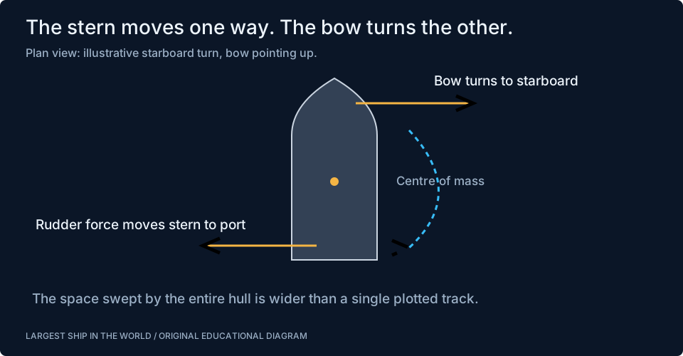
A rudder acts as a hydrofoil. When angled to the incoming flow, it develops a transverse force. Because that force is applied near the stern, away from the ship’s centre of mass, it creates a turning moment. In an illustrative turn to starboard, the stern initially moves towards port while the bow swings towards starboard. The hull then develops its own hydrodynamic forces as its angle to the flow changes.
Rudder performance depends on its area, shape, angle and the local flow, including propeller wash. Increasing angle indefinitely does not produce proportionally increasing useful force. Flow separation, drag and structural loading intervene. The practical design balances course keeping at service speed with manoeuvring at lower speed. It is therefore misleading to picture the rudder as a wheel mechanically dragging the bow around a bend. It starts a force-and-motion response involving the whole immersed hull.
Sources: [1] Wärtsilä: rudder ↗
The ship sweeps a wider space than its track
On a map, a vessel is often reduced to one point and a heading line. A real ship occupies a long rectangle-like footprint that rotates and translates. The path of its bow differs from the path of its stern, and both differ from the track of its centre. A photograph of the bow clearing an obstruction does not prove that the stern will clear it a few moments later.
A useful tabletop demonstration uses a ruler. Place its centre on a curved line, then rotate it to follow the line’s changing direction. Each end sweeps across a different area. Now add sideways drift while rotating the ruler. The occupied envelope grows again. Ship-handling tools describe related quantities such as advance, transfer and tactical diameter, but the basic insight is geometric: safe clearance must account for the entire hull throughout the manoeuvre, not just one plotted position.
Why control changes as speed falls
At lower forward speed, the natural flow past a conventional rudder decreases. Propeller wash can still help, but producing that wash may also create unwanted forward thrust. A ship approaching a berth therefore faces a balance between maintaining steering authority and reducing momentum. Its design and equipment determine which combinations are available. Stopping the main engine does not automatically make all aspects of the approach easier.
Tunnel thrusters create transverse thrust near the bow or stern, providing a useful additional control at low speed. Their effectiveness is not constant under every inflow and operating condition. Wind acting on a tall side can also be significant when the vessel is moving slowly. A cruise ship with substantial superstructure presents a different above-water profile from a deeply loaded tanker. The handling plan brings these forces together rather than treating thruster power as a universal substitute for tug assistance.
Sources: [5] Kongsberg Maritime: thrusters ↗
Pods change the direction of thrust
A steerable propulsion pod can direct its propeller thrust through different angles, combining propulsion and manoeuvring functions. With more than one propulsor, different thrust directions can create a sideways force, a turning moment or a combination. The electrical connection makes the location of the generating engines less directly tied to a long mechanical shaft line. That flexibility is one reason the arrangement appears on many passenger and specialist vessels.
It still has limits. Available electrical power, permitted steering rates, propeller interaction and the manufacturer’s operating envelope constrain what the system can do. Multiple pods do not mean that every combination of speed and angle is acceptable. The useful comparison is between complete systems: engines or generators, controls, propulsors, hull and intended service. A pod-equipped ship remains a large mass in moving water, so its ability to direct thrust does not abolish inertia.
Tugs add forces where the ship needs them
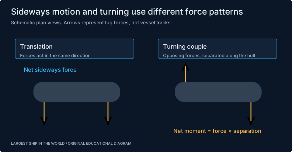
A tug working near the bow can create a different turning effect from the same force applied near the stern. Two tugs pushing sideways in the same direction can help translate a ship. Forces in opposite directions at opposite ends can rotate it. The distance between a force and the centre of rotation matters, so the position of a tug is part of the manoeuvre rather than a minor detail.
For an original simplified example, two opposite forces of 300 kilonewtons separated by 150 metres create a couple of 45 million newton-metres. Their sideways forces cancel in that ideal diagram, while their turning moments add. Real tug forces, towline angles, hull contact points and environmental loads vary continuously. The example explains the distinction between moving sideways and turning; it does not specify a tug plan. Effective work also depends on clear communication and agreed commands among the pilot, bridge and tug crews.
Shallow water changes the problem
A ship moving in restricted depth alters the flow through a smaller waterway around its hull. The associated pressure changes can cause additional sinkage and trim, commonly called squat. The amount depends on the vessel and channel as well as speed. A static draft measurement therefore does not fully describe the clearance beneath a ship moving through shallow water.
Banks and nearby hulls also affect the flow field. These interactions can produce forces and moments that are absent from an open-water trial. The consequence for a reader is straightforward: a canal transit cannot be evaluated from ship length and waterway width alone. Draft, depth, speed, bank clearance and handling response also matter. Our canal-fit comparison identifies dimensional constraints, while the ship’s approved operating information and local authority procedures address the much more detailed passage decision.
Sources: [4] Wärtsilä: squat ↗
Wind, current and anticipation
A manoeuvre is usually prepared before its most visually dramatic stage. Speed can be reduced well before the berth appears close. Tugs may be positioned before the ship enters a confined basin. The bridge and pilot discuss expected movements, machinery readiness and the points at which a plan would need to change. This work is less photogenic than a tug pushing against a hull, but it gives the visible operation its margin.
Wind and current are not simply extra arrows added at the end of a drawing. They affect how a vessel approaches the manoeuvre, which side needs room and how quickly an error can grow. For a tall ship, wind force and its point of application can create a considerable yawing moment. For a long ship, a current that varies along the hull can matter differently from a uniform flow. Conditions and responses are monitored as the manoeuvre develops.
What a manoeuvring trial actually tells us
Turning-circle and zig-zag tests examine different aspects of response. A turning trial records the space used after a specified rudder command. A zig-zag test explores how the ship responds when the rudder is reversed after reaching a prescribed heading change. A stopping trial records the response after an astern command from a defined initial state. These are related measurements, not interchangeable rankings of how easy a ship is to drive.
IMO’s MSC.137(76) provides a framework for evaluating manoeuvrability. Trial results belong with their conditions and definitions. A graph should identify whether distance is measured along the original course, across it or along the actual track. A number detached from that explanation can create false confidence. The useful question is not simply whether a vessel turns tightly, but which aspect of its response was measured, at what loading and speed, and how those results inform its intended service.
Sources: [2] Wärtsilä: manoeuvring characteristics ↗ [3] IMO: Standards for Ship Manoeuvrability, MSC.137(76) ↗
Read the next harbour video differently
Start by identifying the ship’s heading and its actual movement. Look for the stern sweeping out, a bow thruster disturbing the surface, tug positions and changes in propeller wash. Notice whether the vessel is still moving forward while a braking command may already be active. These observations reveal the system at work without pretending that an outside observer can reconstruct every bridge decision from a short clip.
Then connect the scene to the deeper topics. Ballast and cargo change draft and inertia. Hull form affects directional response. Propulsion arrangement shapes the available thrust. The Ever Given case study shows why a narrow-waterway event needs evidence from an investigation rather than a single explanation based on wind. The interactive cutaways and ballast lab let you explore these connections, while keeping educational demonstrations separate from vessel-specific operating instructions.
Sources: [7] Panama Maritime Authority: Ever Given investigation, hosted copy ↗ [8] IMO: ship design and stability ↗
Watch the engineering in action
Sources & further reading
An editorial explainer based on the technical, research and industry references below.