Ship propulsion explained: engines, electric drives, pods and the next generation
Follow the energy from the fuel tank to the water, and understand the choices that shape a ship’s machinery, manoeuvrability and emissions.
By Alykhan Virani · 12 min read · Published
More in Shipbuilding →Running a giant series →Try the engineering lab →
Contents · 16 sections
Start with the energy path
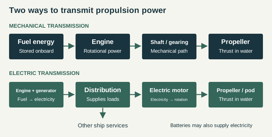
A propulsion system has several jobs: obtain energy, convert it into useful power, transmit that power and turn it into thrust. Those jobs need not be performed by one machine. An engine may rotate a propeller shaft mechanically, or it may turn a generator whose electricity feeds a propulsion motor. A battery stores electricity; a propeller transfers energy to the surrounding water. Calling a vessel “electric” therefore describes only part of its arrangement. The first question is where its electricity comes from. The second is how that electricity reaches the propulsor. Keeping those questions separate prevents a surprisingly common misunderstanding: an electrically driven ship can still burn fuel throughout a voyage.
Sources: [1] Wärtsilä: marine diesel engines ↗ [2] Wärtsilä: electric propulsion systems ↗
Mechanical propulsion: an engine linked to a shaft
In a mechanical arrangement, rotational power travels from the engine to the propeller through a shaft line, with gearing where required. The machinery layout must accommodate that mechanical connection. An engine specification and a propulsion specification consequently answer different questions: one describes the power-producing machine, while the other describes the complete route to the water. Wärtsilä notes that a marine diesel engine can provide mechanical propulsion, generate electricity, or perform both roles depending on the design. The word diesel alone does not establish whether a vessel has a direct mechanical drive or an electric transmission. When reading a ship profile, look for the engine, gearbox or shaft arrangement and propeller as separate entries.
Electric propulsion: a power station connected to motors
Electric propulsion inserts generators, electrical distribution and motors into that energy path. Wärtsilä describes systems supplied by generating sets, batteries or a combination of energy sources. This creates flexibility in the relationship between the power source and the propeller: their speeds are no longer tied together by a continuous mechanical shaft. It also means the propulsion system is part of the vessel’s wider electrical design. The important distinction is between installed generating capacity and power delivered to the propulsion motors. They are different quantities, and a headline figure for the ship’s power plant should not automatically be labelled propeller power. Electrical conversion also introduces equipment and losses, so an electric architecture is a design choice rather than a guarantee of lower fuel consumption.
Sources: [2] Wärtsilä: electric propulsion systems ↗
Podded propulsion: putting the motor outside the hull
ABB’s Azipod places an electric motor in a submerged, steerable pod outside the hull. The unit can direct thrust through 360 degrees. Instead of relying only on a fixed propeller and a separate rudder, the propulsion unit itself changes the direction in which it pushes or pulls the ship. That is why podded propulsion is often discussed in connection with manoeuvrability. Azipod is a particular ABB product family, not the generic name for every thruster. Nor does every electrically propelled ship have pods: an electric motor can also drive a conventional shaft arrangement. Motor location, power supply and steering method are three distinct pieces of the specification.
Fixed pitch, controllable pitch and sideways thrust
Pitch describes the geometry of a propeller blade. A controllable-pitch propeller changes blade angle, allowing the propulsion system to adjust how the propeller loads the engine. Wärtsilä’s CPP systems coordinate engine speed and pitch for operating conditions. This is separate from azimuth steering: changing blade pitch and rotating the direction of an entire propulsion unit are different actions. A tunnel thruster adds another distinction. It directs water across the vessel through a transverse tunnel to assist manoeuvring. A ship can have tunnel thrusters alongside its main propulsion equipment. Counting all the propellers visible in a drawing without identifying their jobs can therefore give a misleading picture of how the ship travels at sea.
Sources: [4] Wärtsilä: controllable-pitch propellers ↗ [8] Wärtsilä: thrusters ↗
Hybrid propulsion: ask what is being combined
Hybrid is a broad description. One vessel might combine engines with batteries; another might combine a mechanically driven propeller with electrically powered pods. Wärtsilä’s CODED concept is an example of that second arrangement. The practical question is which operating modes the combination supports. Can stored energy supply a short demand peak? Can an electric motor assist a mechanical drive? Can the ship use stored power without running its engines, and under what conditions? A useful technical description names the equipment and explains the energy flow in each mode. A hybrid label without those details says very little about range, fuel use or the amount of time spent operating without exhaust emissions.
Sources: [5] Wärtsilä: marine hybrid systems ↗ [9] Wärtsilä: combined mechanical and electric propulsion ↗
Batteries: distinguish power from energy
Battery power, measured in kilowatts or megawatts, describes how quickly energy can be delivered. Stored energy, measured in kilowatt-hours or megawatt-hours, describes the quantity available. Consider a deliberately simplified example: a usable 10 MWh store supplying a constant 5 MW load lasts two hours before accounting for losses or reserve requirements. Double the load and the ideal duration halves. That arithmetic explains why a large peak-power rating is not evidence of a long battery-only range. Wärtsilä identifies peak shaving, in which storage handles short increases in demand, as one role for marine batteries. This can be valuable even when a vessel’s entire voyage cannot be supplied from storage. Any real endurance estimate also needs hotel demand, operating limits, conversion losses and the energy held in reserve.
LNG and other fuels do not identify the propeller system
A fuel label and a propulsion label belong on different lines of a ship’s specification. LNG describes stored liquefied natural gas, while electric propulsion describes a way of transmitting power. They can coexist. The same distinction applies when assessing announcements about alternative fuels: find out what produces power, how it is distributed and what equipment turns that power into thrust. IMO’s methane guidance explains LNG’s cryogenic storage and the issues associated with methane as a marine fuel. A change in fuel can affect tanks, supply equipment and operating arrangements without automatically determining whether the ship uses pods or a conventional shaft. “Alternative fuel” should therefore begin a technical inquiry rather than serve as its conclusion.
Sources: [6] IMO: methane as a marine fuel ↗
Emissions: draw the boundary before comparing claims
The motor in an electric pod has no combustion exhaust, but the power source elsewhere on the ship may have one. A fair comparison also asks what happened before the energy arrived onboard. IMO’s lifecycle approach distinguishes well-to-tank emissions from producing and supplying the fuel, and tank-to-wake emissions from its use aboard ship. The combination is well-to-wake. Methane emissions are relevant to an LNG assessment, so a claim about lower carbon dioxide alone does not settle the total greenhouse-gas comparison. Similarly, a battery-powered operating period should be described with its charging source and assessment boundary. Comparisons are most useful when they state the same operating task, the same emissions boundary and the assumptions behind the calculation.
Sources: [6] IMO: methane as a marine fuel ↗ [7] IMO: lifecycle greenhouse-gas assessment ↗
How the shipyard proves the machinery works
Installing the engine or pod is not the final step. The complete propulsion plant must operate as an integrated system with its controls and electrical or mechanical connections. Bureau Veritas’s classification rules include dock and sea-trial provisions for propulsion machinery; electrical checks and manoeuvring tests are among the relevant requirements. The applicable programme depends on the vessel and its class requirements. This matters when reading a construction announcement: a photographed installation establishes a physical milestone, while a successful trial provides a different kind of evidence. Neither a dramatic float-out nor the presence of a large engine by itself demonstrates the completed ship’s performance.
Sources: [10] Bureau Veritas: machinery and propulsion testing rules ↗
Follow the losses: a worked energy-balance example
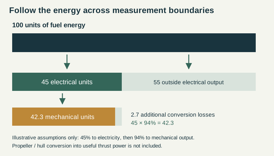
A system diagram becomes more useful when the quantities are labelled. Imagine a hypothetical electrical plant receiving 100 units of fuel energy. Assume, solely for this example, that 45 units become electrical energy at the generator terminals. If electrical distribution and motor conversion together retain 94 percent of that amount, the resulting mechanical output is 42.3 units: 45 multiplied by 0.94. The remaining energy has not vanished. It leaves the selected useful-output path through losses and other energy flows.
These percentages are illustrative assumptions, not performance figures for a named engine or vessel. They show why efficiencies in series are multiplied rather than added. They also show why the boundary matters: generator output and motor output are different measurement points. To continue the calculation into useful thrust power, another propulsion-related assessment would be required. The 42.3 units at the motor do not mean that 42.3 units have become useful forward motion of the vessel.
A mechanical alternative should be compared using the same starting energy, operating condition and output boundary. Counting one architecture’s full chain while counting only another architecture’s most efficient component would produce a misleading result. The energy-balance diagram is intended as a method for reading claims, not as a verdict that one transmission arrangement always wins. Real comparisons need the actual equipment maps and the vessel’s operating profile.
The propeller and hull must work as a pair
The propeller operates in water affected by the ship’s hull. Its inflow is therefore not simply the undisturbed flow that would exist far from the vessel. As blades rotate through a varying flow field, loading can change around the revolution. Wärtsilä’s discussion of propeller excitation identifies the relationship between blade loading, cavitation and forces. This helps explain why a propeller is designed for an installation rather than selected only by matching an engine’s power rating.
Cavitation involves vapour formation in low-pressure regions of the flow. Its behaviour matters for noise, vibration and the condition of surfaces exposed to collapsing cavities. A cavitation tunnel allows investigators to examine a propeller under controlled conditions while measuring thrust and torque. The tests support design decisions; they are not evidence that every visible bubble behind a ship represents the same phenomenon or the same engineering problem.
For a shipyard, the practical implication is that machinery installation, hull form and propulsor design are connected. A different propeller geometry may affect loading and vibration, while the available space constrains what can physically be installed. The best arrangement cannot be determined from diameter or blade count alone. A technically useful specification therefore connects the propulsor to its design conditions and the surrounding vessel, instead of presenting it as an isolated piece of hardware.
Sources: [11] Wärtsilä: propeller cavitation testing ↗ [12] Wärtsilä: propeller excitation forces ↗
One ship, several operating conditions
A propulsion plant rarely spends its entire life at one constant demand. Transit, manoeuvring and time alongside can produce very different combinations of propulsion and other electrical loads. Wärtsilä’s hybrid discussion emphasises matching the system to an operating profile. That is a better starting point than choosing equipment from a single peak-power number.
Consider three fictional operating points. During transit, propulsion might dominate the load. During slow manoeuvring, the direction and responsiveness of thrust may matter more than sustained forward speed. Alongside, main propulsion can be inactive while ventilation, lighting and other services still require power. These examples explain the categories; they do not provide measured loads for a particular cruise ship.
An energy-management system can coordinate available sources and consumers according to the selected arrangement. Wärtsilä distinguishes this optimisation task from simply switching generating sources on and off. A battery, for example, may absorb or supply short variations while engines operate under different loading conditions. Whether this reduces total fuel use depends on the full cycle, including how the battery is recharged. Looking only at the discharge period would omit part of the energy balance. This is why a meaningful efficiency claim needs an operating scenario, not merely a picture of the installed equipment.
Sources: [13] Wärtsilä: hybrid-system operating profiles ↗ [14] Wärtsilä: energy management for ferry systems ↗
Installed capacity is not the same as available power in every circumstance
Adding the nameplate ratings of all installed units gives one number, but it does not automatically establish the power available for every task at every moment. Some capacity may be needed for non-propulsion services. Equipment may be unavailable for maintenance. Electrical distribution and control arrangements also determine which sources can serve which loads. An equipment list and an operating capability statement are therefore different documents.
Use a simplified imaginary plant with four generating sets, each rated at 10 MW. Its summed rating is 40 MW. If one set is unavailable, the sum of the remaining ratings is 30 MW before other limitations are considered. If ship services require 8 MW, subtracting that assumed demand leaves 22 MW at this simplified accounting boundary. Losses, reserve requirements and distribution constraints would still need assessment before calling that amount propulsion output. The example is arithmetic, not a description of an approved redundancy arrangement.
This distinction matters when a promotional figure is compared with a vessel’s speed or manoeuvring performance. The total installed rating does not explain how power is allocated or what remains following a particular failure. A complete assessment needs the system design and its operating limits. Readers can avoid many errors simply by retaining the label attached to each figure rather than shortening every large number to “the ship’s power.”
What a propulsion diagram leaves out
The clean arrows in a schematic deliberately hide physical detail. A real installation also needs cooling, lubrication where applicable, monitoring, protection, structural support and access for inspection and maintenance. A motor placed in a pod changes the physical arrangement, but it does not remove the need to service the installation. An engine located inside the hull still has to connect to the equipment that supports its operation.
A diagram is most useful when its omissions are stated. Our energy paths describe the main conversion route, while the worked balance describes selected numerical boundaries. Neither is a wiring diagram, an installation drawing or a complete operational procedure. The figures are designed to help the reader ask more precise questions of a vessel’s specification.
When moving from this guide to a particular ship, look for the supplier’s installation-specific documentation and the builder’s particulars. Confirm the number and rating of units, the purpose of those ratings, the type of propulsor and the stated operating capability. Keep future-fuel readiness separate from actual operation on that fuel. This final step connects the broad engineering principles to evidence about the vessel rather than allowing a familiar technology name to fill every gap in the record.
A practical way to read a propulsion specification
Read the equipment list in order: energy source, engine or generating plant, transmission, propulsion motor if fitted, propulsor and steering arrangement. Then record the units attached to each number. Megawatts of generating capacity, megawatts of motor output and megawatt-hours of stored energy cannot be used interchangeably. Finally, ask what the ship is designed to do. A system should be assessed against its operating pattern, manoeuvring needs, electrical demand and maintenance requirements. This guide explains architectures rather than assigning an unverified machinery package to every ship in our directory. For a named vessel, use the builder’s or equipment supplier’s specific documentation before drawing conclusions about its installation.
Watch the engineering in action
Sources & further reading
An editorial explainer based on the technical, research and industry references below.
- Wärtsilä: marine diesel engines ↗
- Wärtsilä: electric propulsion systems ↗
- ABB: Azipod electric propulsion ↗
- Wärtsilä: controllable-pitch propellers ↗
- Wärtsilä: marine hybrid systems ↗
- IMO: methane as a marine fuel ↗
- IMO: lifecycle greenhouse-gas assessment ↗
- Wärtsilä: thrusters ↗
- Wärtsilä: combined mechanical and electric propulsion ↗
- Bureau Veritas: machinery and propulsion testing rules ↗
- Wärtsilä: propeller cavitation testing ↗
- Wärtsilä: propeller excitation forces ↗
- Wärtsilä: hybrid-system operating profiles ↗
- Wärtsilä: energy management for ferry systems ↗